Build your own SD2IEC with or without PCB (in english)
25 agosto, 2017
by Uctumi
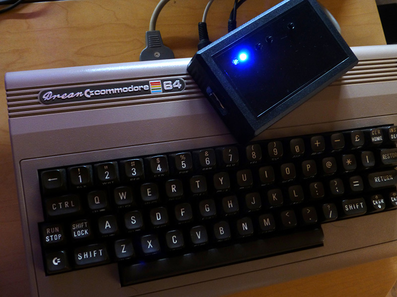
The “Punga” SD2IEC has a new version, this time with a simplified design and build without losing functionality.
NOTE: This project is deprecated, as it has been surpassed by PI1541 based on raspberry PI and much more compatible with all C64 software, as the emulation of the disk drive is much better. We recommend you build that instead, for more info on how to build it go to: https://cbm-pi1541.firebaseapp.com/
Features of this project
- It doesn’t require a PCB board, so you save the costs of ordering a custom built one or having to purchase the materials to build it (quite dirty, btw)
- We use an Arduino Micro SD module very easy to source and which already includes a voltage regulator.
- Can be assembled using recycled components and parts, reducing costs and making it more accesible for everybody.
This project is based in the SD2IEC by Lars Pontoppidan, and is compatible with current and future firmware files for this version. It has practically the same functionality as any SD2IEC you can purchase on Ebay for $40 or more.
You don’t need too much knowledge of electronics or too many tools, you can use many things you already have at home.
To simplify it even more the project will be split in two, the mandatory components that are required for minimal functionality (saving and reading files from an SD Card and communicating with the computer). And optional components that are recommended like buttons to switch folder and image files and activity leds.
NOTICE: I’m not responsible for any damage that may occur to your devices by following this guide, do it at your own risk.
BILL OF MATERIALS
MANDATORY
1x ATMEGA1284P-PU (o ATMEGA644A-PU if you can’t get 1284, also ATMEGA644P-20PU)
1x socket DIP 40
1x 100nF capacitor
1x 8MHz crystal
2x 22pf o 33pF capacitor
1x conector DIN 6 male
1x edge conector 6 pins pitch 3.96mm
1x MICRO SD Arduino module with REGULATOR <-important
Some strands of copper wire (can be collected from a regular electricity wire)
1x piece of flat cable, or any cable with 6 wires (you can recycle a disk drive cable, vga, printer cable, you can also use separate wires but it can be a bit messy)
1x A rectangular piece of cardboard, used x-ray board, paper, plastic board, etc. (you can also make it in a test board if you understand the schematics well)
1x BOX or CASE (recycled, built, bought) in which to assemble the device in.
OPTIONALS
1x LED green
1x LED red
3x momentary switch
2x 560 ohm resistor
1x 10000 (10k) ohm resistor
Some thin wire pieces
1x A smaller rectangular pieces of plastic, cardboard, paper, etc.
Pieces of heat shrinking tube or insulation tape.
TOOLS: 30-40W soldering iron, something to clean soldering iron tip like sponge or steel wool, solder, cutter, pliers, clippers, bodkin or needle.
THE BOARD
Despite not using a PCB, this project does have a schematics and we’re going to layout the components in a “pseudo PCB” in order to organize it a little bit and avoice failures. This is the schematics (Please notice that the pin numbers are not the real numbers of the IC, but a number I put so it’s easier to count when assembling the board).
You can download the PDF so you can print it clicking here.
This schematics explains how to connect all that we need for the SD2IEC to work. You will now
download the actual size PDF version from this link and you’re going to print this without scaling (be careful) so we can use it as reference.
We put the print under our board and with a needle we start punching holes following the green marks in the schematics.
If you can’t get a plastic board you could just use the print as PCB. I haven’t tried it but I think it can be made to work. Specially if it’s a thick paper or cardboard.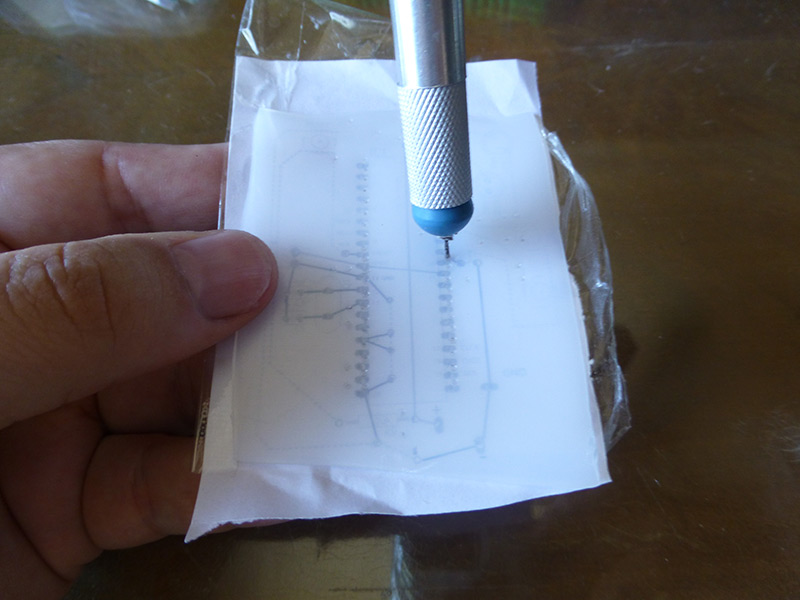
Once the board is punched we’re going to insert he components, as you can see these’re not many, specially if you don’t connect buttons or leds.
Then we solder behind it as per the schematics, we use the wires that come with each component to connect with each other and to the socket, as if these were the conductive tracks of an imaginary PCB.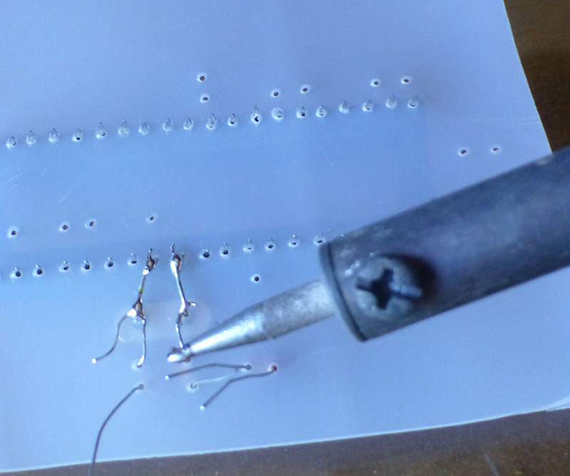
In the schematics you will notices a wire that is layed out in a zig zag pattern, this is a thin copper wire that carries the negative voltage connection and you have to “thread” it at specific points, it goes a bit over and a bit under the board, and it has a function everyplace it goes.
It connects pins 20, 16 and 11 from on side of the IC and pin 10 from the other side (see schematics). It also gives negative voltage to the optional buttons.
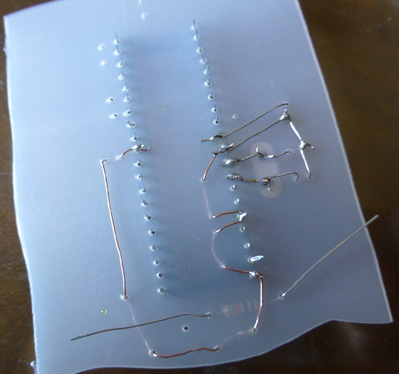
In the image below you’ll see a thicker wire, this is carrying the positive voltage. It’s not necessary for this wire to be this thick, but I used this one because it has better conductivity and it makes the whole assembly more stable.
As you can see I can’t be praised by my tidiness, but I guarantee you that if everything is connected properly your SD2IEC will work.
It’s not a bad idea to put some hot glue in the joints to stabilize and isolate them, but it’s better to do that after the SD2IEC is tested and known to work and we’re just about to install it in its case.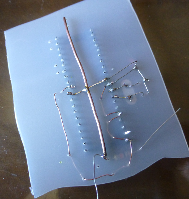
This is how the assembly begins to take shape, the resistors you see there are for the buttons and leds.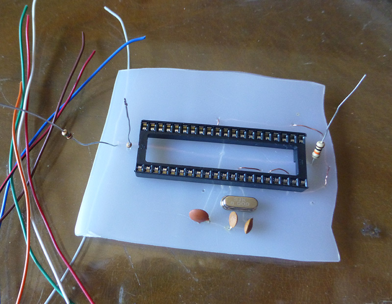
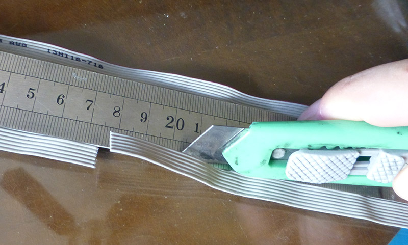
CONECTING THE ARDUINO MICRO SD MODULE
To do this we recycle a flat wire from an old floppy drive. We only need 6 wires, so we can keep the rest of the flat cable for other projects.

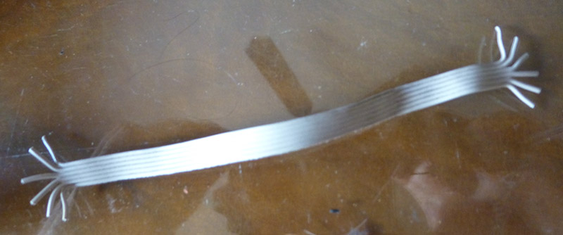
Once the wires are cut and stripped we solder them to the board according to the schematics.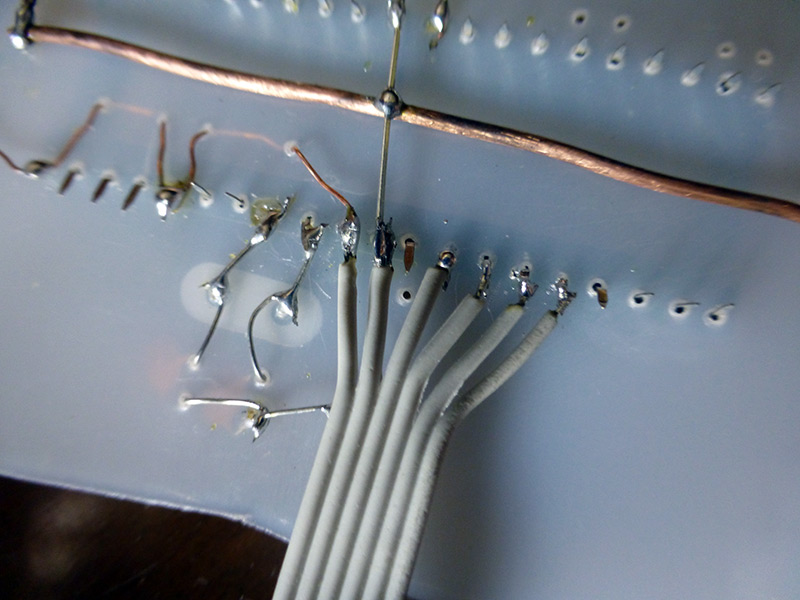
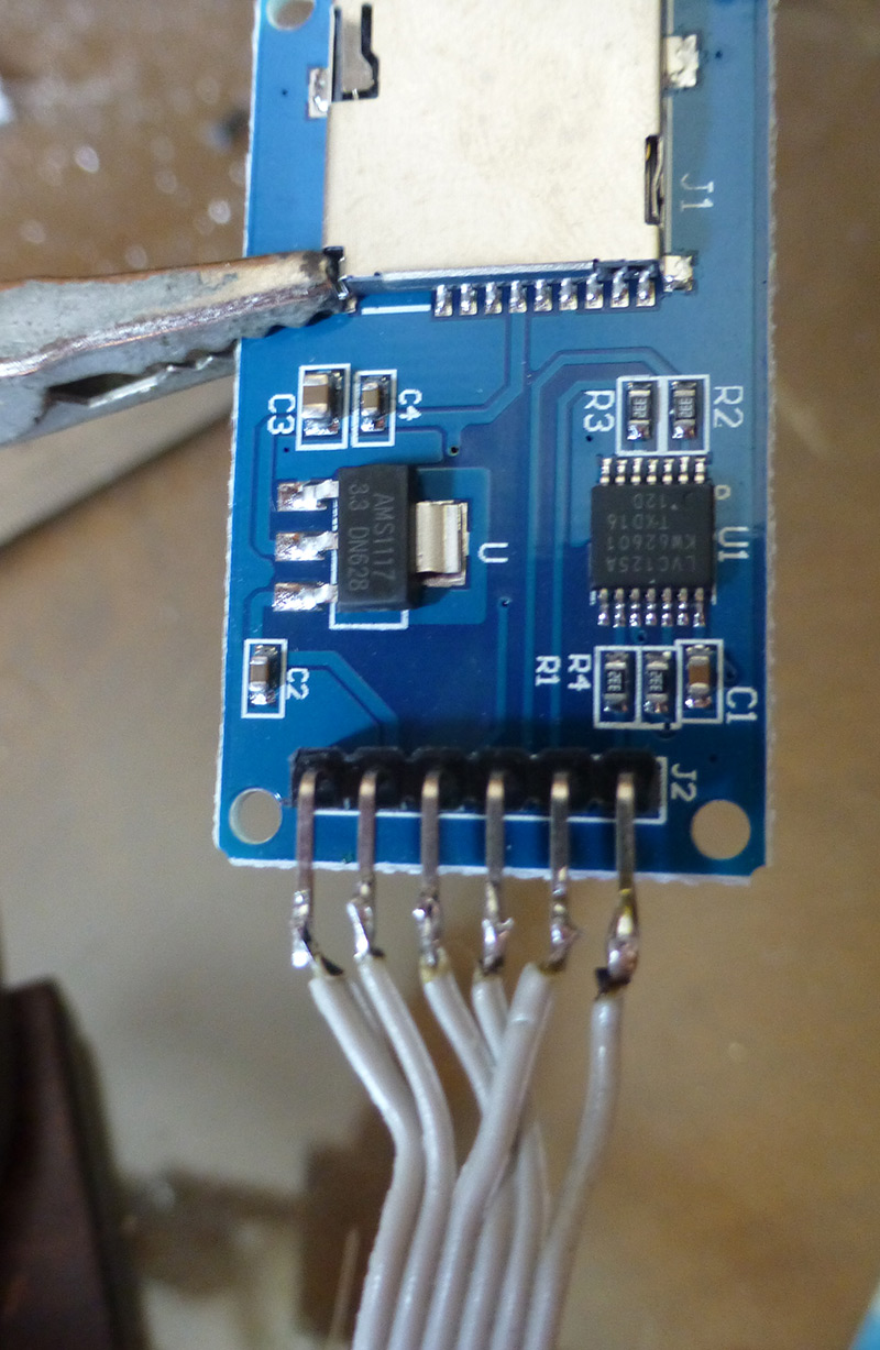
Then we connect these wires to the arduino micro SD module as per the schematics. Follow the labels in the arduino module itself. (Usually in the reverse side you’ll find them). If you use an SD module instead of micro SD it’s a bit different but you just have to remember to connect the 5V pin and not the 3.3V one.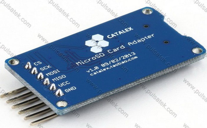
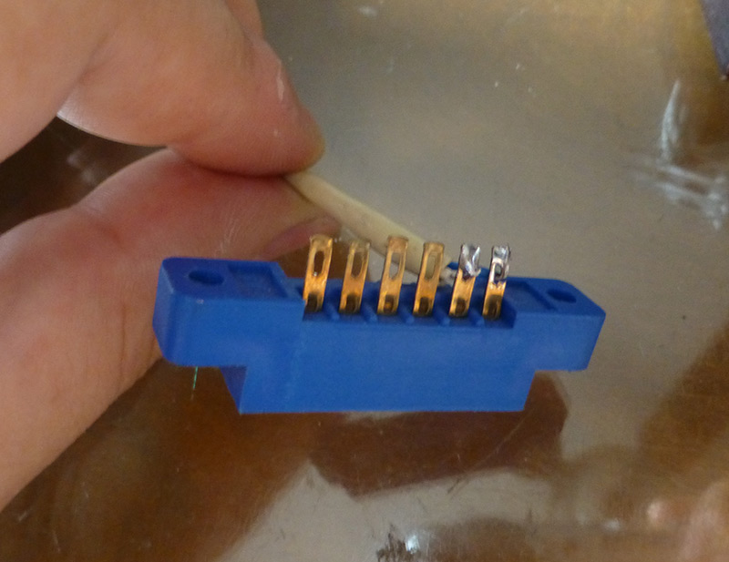
Then we solder the edge connector for power as per the schematics. The negative is the last pin and the positive is the previous one.
You will then connect these wires to pins + and – of the board as per the schematics.
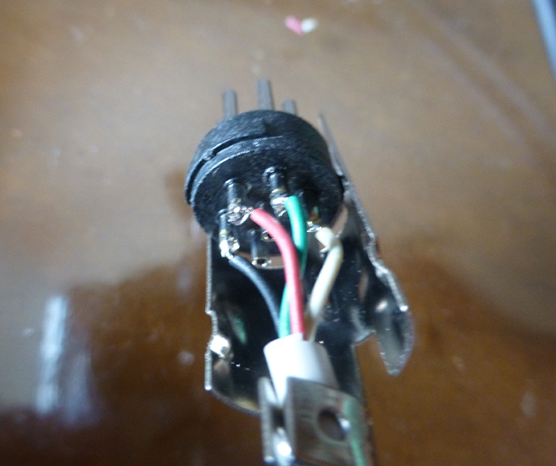
We then solder the DIN 6 connector that will go to the serial port of our commodore computer according to the schematics which is drawn as viewed from the connector side of the computer. We connect pins CLK, DATA andATN which are 17, 18 and 19 of the right side of the IC.
(remember I’m not counting the same way as in the reference sheet of the IC).
PROGRAMMING THE ATMEGA IC
We only need to program the Atmega IC, you can also get it programed or ask for someone to do it for you. Below you will find a guide to do it yourself.
The ideal is to have a “programmer” which is an already prepared circuit in which we insert the chip and then conect it to a PC via USB.
But because this is the 3rd world SD2IEC and we’re not gonna buy that, there’s a cheaper alternative that is using the old printer port from an old PC.
What we need:
– A PC with a printer port (normally pentium III or older, maybe a P4) – A 25 pin parallel cable for priner port (the one with which you used to connect your printer in the 80’s and 90’s)
Then you need to connect the pins in the Atmega IC to the pins in the parallel cable as per this diagram:
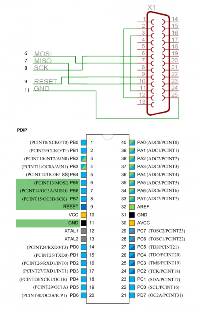
The cable used needs to be shorter than 12 inches, because a longer cable could cause trouble. Resistors are not necessary as other diagrams suggest. If you’re using recycled wire use a multimeter to test which pin corresponds to wich wire. Usually pins 18-25 are all connected to GROUND. Pay attention there are some cables that are inter connected, just solder those together and cover them with insulation tape.
The parallel connector has little inscriptions telling you the pin number, so you can use that as a guide. Only 5 pins are connected to the IC. MOSI, MISO, SCK, RESET, GND. Pay attention to the notch in the chip to identify the pin number (this time it’s according to the official sheet).
What I did to make things easy for me is to use the very same PCB where I’d mount the SD2IEC and solder those 5 pins from behind directly to the parallel wire. After the IC is programmed you can then desolder them.


For programming the SD2IEC has to be powered and built (the SD card is not needed). The power needs to be strictly 5V so you don’t damage the parallel port. You have to take it directly from the same PC you’re using to program, from a USB, PS/2 port or joystick port.
We’re going to use AVRDUDE software, works in Linux, Windows XP 32 bits and the old Win 98/NT. I did it on Windows XP, so the instructions I will provide are based on that.
If your PC doesn’t have Windows XP installed you can boot it with Hiren’s boot CD and used the option to boot a “Mini Windows XP”.
What we do first is to prepare the PC in which we’re going to program, before even plugin our SD2IEC in.
We have to download and install WINAVR (link), by default installed in C:\ drivein the WINAVER folder followed by version date.
In that folder we’ll find the sub-folder BIN, copy there the image we’re going to program, downloaded from http://www.sd2iec.de get the file sd2iec-current-binaries.zip and use the LarsP version for the corresponding IC 1284 or 644.
There’s a also a firmware with version 10.0.3 and a “bootloader” that allows you to flash a new firmware from the SD card. This is only for Atmega1284 (this firmware doesn’t exist for 644 due to memory contraints) you can dowlnoad it from here
Turn off the PC and preferably unplug it. Once we have the SD2IEC connected to it both the parallel and power wire, turn on the PC.
Inside Windows XP open console RUN > CMD
Enter disk C:\
C: CD\WINAVR (press tab to complete name and press enter)
CD BIN
there type
INSTALL_GIVEIO

This installs a driver needed to access the printer port directly. You should see an OK message like in the picture.
Then enter this command replacing “sd2iec.bin” for the name of the firmware file you’re installing (varies with the version)
FOR ATMEGA1284 avrdude -p m1284p -P lpt1 -c pony-stk200 -U flash:w:sd2iec.bin -U lfuse:w:0xEF:m -U hfuse:w:0x99:m -U efuse:w:0xFF:m
FOR ATMEGA644 avrdude -p m644p -P lpt1 -c pony-stk200 -U flash:w:sd2iec.bin -U lfuse:w:0xEF:m -U hfuse:w:0x99:m -U efuse:w:0xFF:m

Then you should see some texts indicating progress, in approximately 49 seconds the programming should be done and in about the same time it will self-verify itself.
You can copy this line in a .BAT file and put it in the folder so you don’t waste time typing it in case you have to do it many times.
If everything is OK it will tell you so. Then you turn off the PC and unplug everything.
USING A USB PROGRAMMER (Contribution by Cristian Hlavanda)
We need the following:
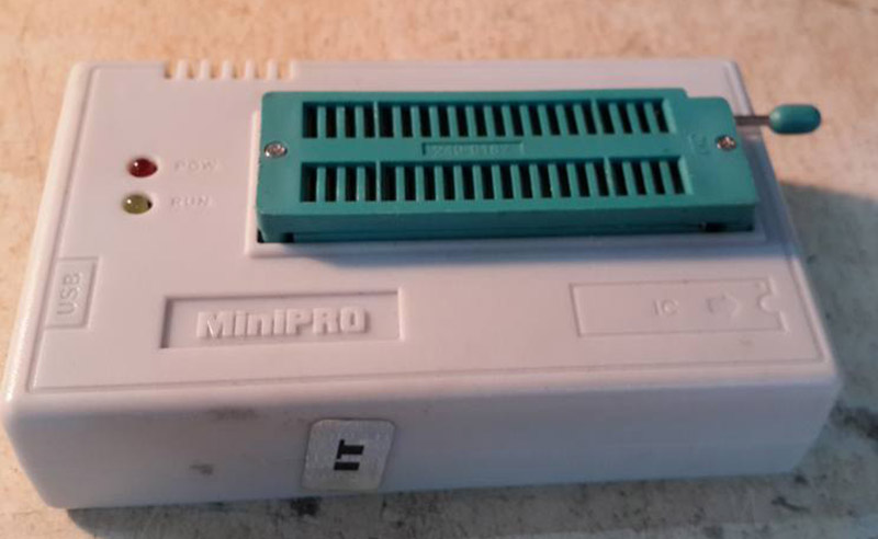
- USB tl866 programmer
- IC Atmega 1284p o 644a o 644p
- SD2IEC Firmware from http://sd2iec.de/sd2iec-current-binaries.zip
- PC

This is very easy and in the end there are a few pictures of the process. First we need to connect the USB programmer to our PC. It has a software called “minpro” which we should’ve installed previously and check that the programmer is being detected. This is done automatically via USB port.
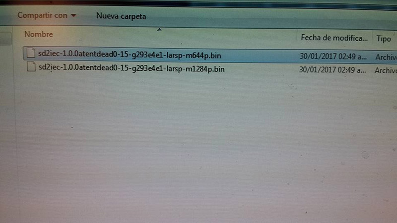
We unzip the file to install in the IC, we’ll only be using “lars-m1284p.bin” or “lars-m644p.bin” depending on our IC version.
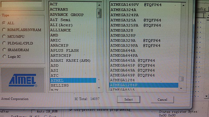
Now we launch the programmer software. We put the IC in the socket making the notches match.


This is important: In the select IC tab we chose “Atmel Atmega1284p or 644p”.
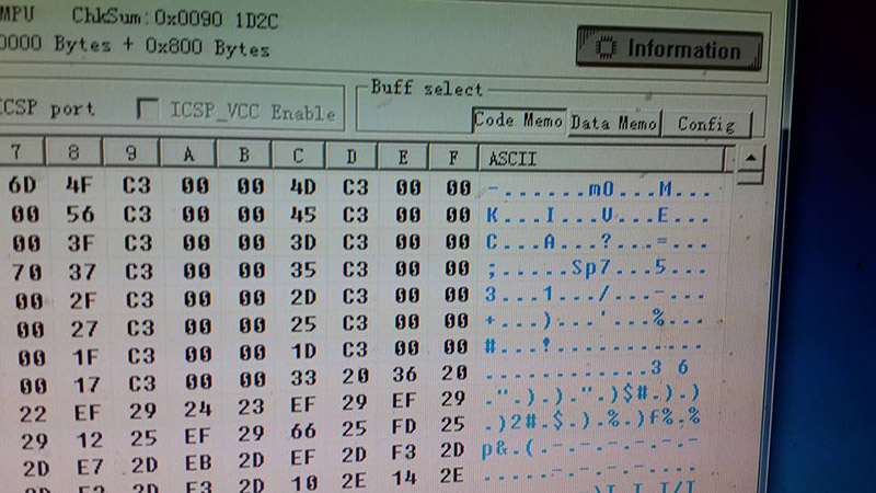
In the open file tab we open the firmware file and we see the memory grid gets populated visualizing the file contents.
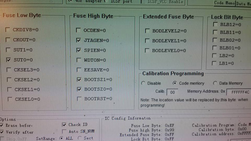
In the “buff select” part to the right we select config and we’ll program the fuses like you see in the following picture.
Then we press the red P button and if everything is OK the programming will be done in seconds.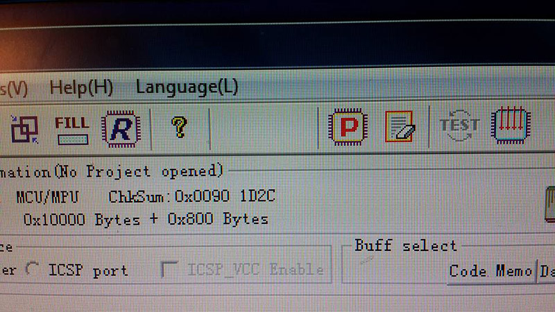
We close the software, remove the chip and enjoy our SD2IEC!
ASSEMBLY
The idea is to put everything inside a case, you can make it yourself, 3d print it, recycle any suitable object, I bought a simple cheap plastic case.
To put it together you can use hot glue, or other type of glue that provides electrical insulation.

LEDS AND BUTTONS MODULE
Up to here we assembled our SD2IEC without optionals. It’s going to work, but not having any indicator led is kinda sad.
For the leds and buttons I made a separate module board, it has 2 led lights indicating operation, reading, writing and errors. And the buttons are used to switch disk images or folders and also to reset (the SD2IEC, not the computer). This method allows you to place the buttons wherever you want in the case.
You can download the actual size PDF here and use it as reference to pierce a piece of plastic board or cardboard.
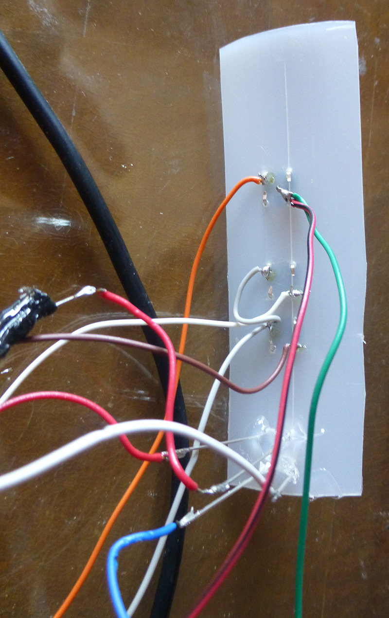
We’re also going to connect the 560 ohm resistors and the 10k ohm resistor as per the schematics at the top of the tutorial. We’ll solder wires to the resistors in order to extend them so they can reach our button module.
We can use heat shrinking tube to insulate where there is stripped wire. We can also use insulating tape instead.
This is what the optional module looks like. You have to then glue this board to the inside of the case, after making perforations. You have to use a good glue, as buttons are going to be pressed, so it needs to hold.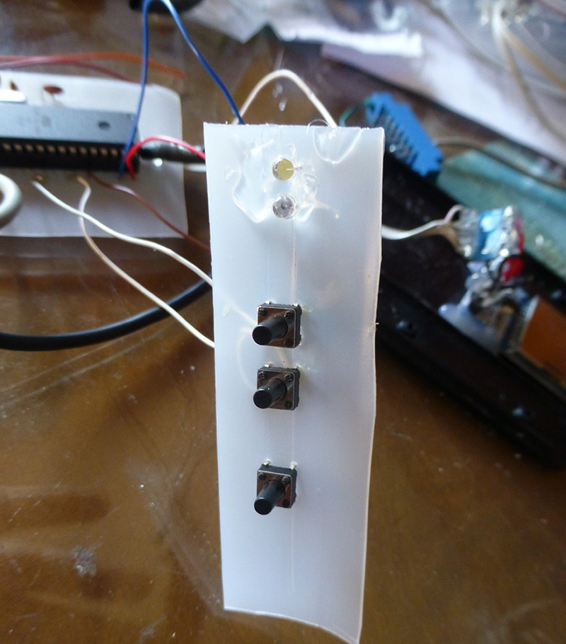
We connect the wires according to the schematics at the beginning of this guide. There are different alternatives to wiring if we understand the circuit. All the buttons are connected to GND (-) at one end. The only button that’s a bit more complex is the RESET one. It’s connected in a “pull-up” configuration with a 10k resistor. Pay attention to the schematics at the top of this guide to understand how it’s wired.
This is more or less how it would look assembled.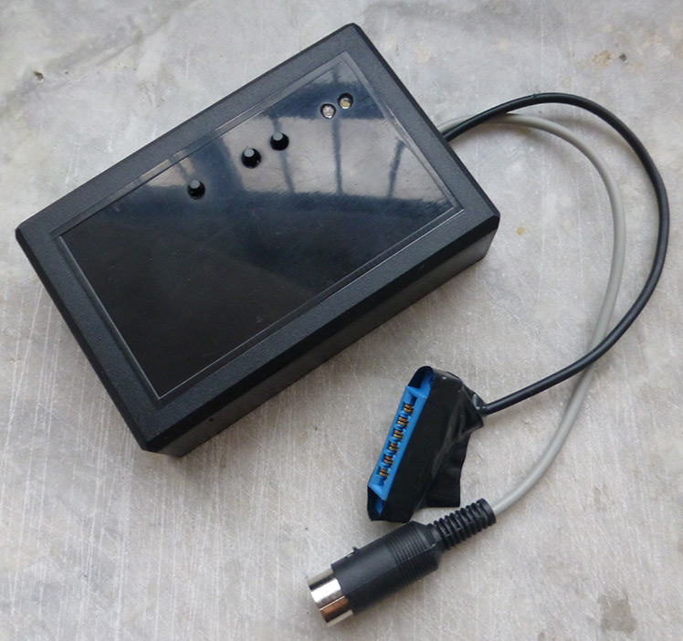
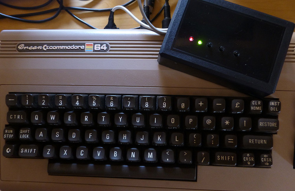
TESTING THE SD2IEC
Contect your SD2IEC to a power source and a C64. Turn on C64. Type in this program:
10 OPEN15,8,15:INPUT#15,A$,B$,C$,D$ 20 CLOSE15 30 PRINT A$,B$,C$,D$
Type RUN <return> and you should see something similar to this: 
If this pops up, it means the SD2IEC is responding fine. Now you should try inserting a FAT32 formated SD card with some files inside.
Type: LOAD”$”,8 <return>
LIST <return>
and we should see the directory listing

That’s it! I hope you can do it and it works!
Greetings:
Rico for helping with PCB design, Riq for bringin the Atmega1284P and Naku for choosing the simplest LarsP design.
If you want to contact me send me an email to my gmail address at uctumi at you know, etc.
ANNEX: COMMANDING YOUR SD2IEC
You will find a command guide in english at this link.
File browser To go around the file structure of the SD card and make it easy to mount disk images and load executables using a file browser is recommended. There are several ones. The simplest and most used is the CBM file browser. I also had good results with SDBrowse. But it’s got some glitches. SDBrowse is specially useful and fast if you want to copy disk images from your SDCard to a diskette inside a 1541 drive, with just your C64.
AUTOSWAP SD2IEC has 3 buttons. The RESTE button brings it back to the root folder. The other two buttons use the SWAP function. It will swap the disk images while we’re running a game or software, much like it would be if we changed or flipped a real floppy disk.
We can tell the SD2IEC with a command to use a list of images we’d previously defined. We use the command XS:nameofthesawplist.lst
By default if there is no swap list manually defined it will look for a file called AUTOSWAP.LST
This file can contain folder names or images names indistinctively. There can be an AUTOSWAP.LST inside each sub-folder of our SD card.
For example if I want to swap the relative sub-directories: folder1, folder2, folder3, folder4. The contents of my autoswap file should be:
folder1
folder2
folder3
folder4
If I want them to reference to the root directory:
//folder1
//folder2
//folder3
//folder4
FASTLOADERS
The SD2IEC supports several fastloader cartridges (some screw it up so be careful), but there’s also a software fastloader called SJLOAD that works with some executables, specially those that doesn’t have their custom loader.
You load this once you turn on your C64 and once it’s activated everything will be loaded through this system.
The file ! is the standard used for SJLOAD (but can be changed if desired)
To load you use
LOAD”!″,8,1
You can also load an executable and SJLOAD all at once
For example loading it alongside the CBM File Browser for C64:
LOAD”!*FB64″,8,1
Packs to download
Games and file browsers by Sander Souza
Pack with games, file browser and tools by Beamrider (Foro Retrocomputación)
Megapack with games and tools by The Future was 8 bit
Categoria: pvm blog | retro computing | tutoriales
Cerrado a comentarios
This project is deprecated, as it has been surpassed by PI1541 based on raspberry PI and much more compatible with all C64 software, as the emulation of the disk drive is much better. We recommend you build that instead, for more info on how to build it go to: https://cbm-pi1541.firebaseapp.com/